The Capacitor - II
Prerequisites:
- Calculus (Optional)
- The previous Tutorials
- Trigonometry
We're going to town on this so you better gear up, but then again, this is one of the most fun passive components ever, so yeah....
So let's talk about how a capacitor actually works. I' not going to go too deep, since that'll require that you know about electrostatics, which is not really as fun as electronics. EE ftw. The basic construction of any capacitor is basically 2 sheets of a conductive material, sperated by a very small distance, and that distance is filled with some insulator. What happens when you put a voltage across is that the negaive charges on one place will move, and electric charges will accumulate on the other side, and this continues on till the capacitor sort of reaches an equilibrium where the attraction and repulsion of charges kinda balance each other out, and also, the capacitor produces a voltage that effectively cancels out the voltage we put across it.
So let's talk about how a capacitor actually works. I' not going to go too deep, since that'll require that you know about electrostatics, which is not really as fun as electronics. EE ftw. The basic construction of any capacitor is basically 2 sheets of a conductive material, sperated by a very small distance, and that distance is filled with some insulator. What happens when you put a voltage across is that the negaive charges on one place will move, and electric charges will accumulate on the other side, and this continues on till the capacitor sort of reaches an equilibrium where the attraction and repulsion of charges kinda balance each other out, and also, the capacitor produces a voltage that effectively cancels out the voltage we put across it.

Here's a formula that you don't need to remember since you only use it in non-EE scenarios-
$$Q = CV$$
where $Q$ is the magnitude of charge on one of the plates (since both plates acquire equal but opposite charges).
Do you remember the formula I last gave you guys? That's a "variation" of this. Simply differentiate both sides of the equation (For those of you who don't know what differentiation is, it's basically a small change in a variable quantity with respect to a small change in some other quantity), and voila-
$$I = C\frac{dV}{dT}$$
But that's something we already know. Let's go a bit further. Let's say there's a circuit like this-
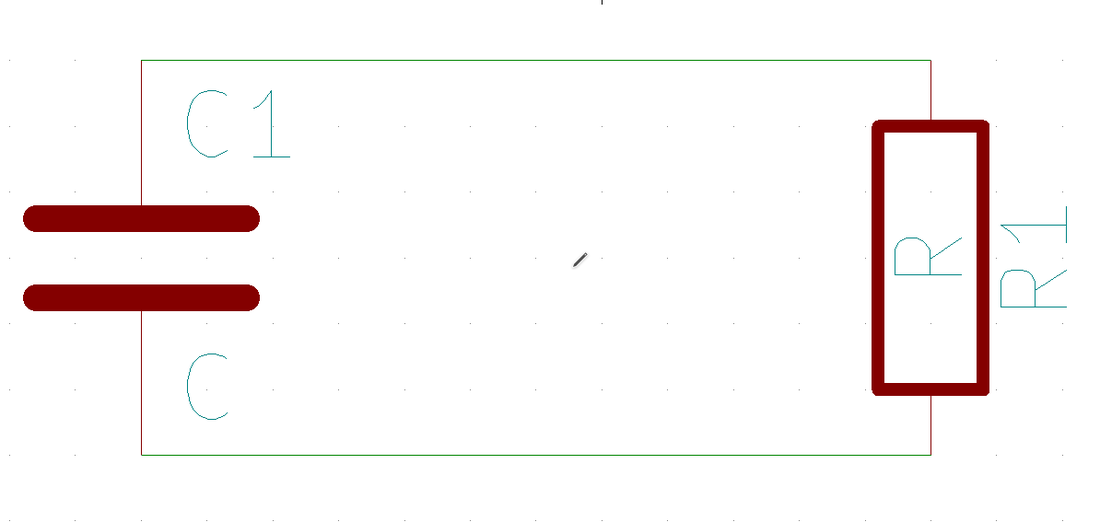
Let us assume that the capacitor was initally charged. Which means the voltage is -
$$V_C = -IR$$
since $V_C + V_R = 0$
Now, we know that-
$$I = C\frac{dV_C}{dt}$$
$$\frac{-V_C}{R} = C\frac{dV_C}{dt}$$
This is a differential equation with the solution-
$$V_C = V_0e^{\left(\frac{-t}{RC}\right)}$$
We call $RC$ the time constant, for reasons I don't know. Also, $V_0$ is the initial voltage across the capactior. You should also look at the graph below (I mean math, yeah, screw that, graphs ftw)-
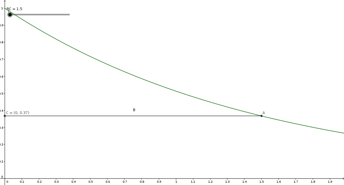
You should be able to see that the cap gets discharged by $63\%$ when $t = RC$
Let's look another circuit (Yay....)-
Let's look another circuit (Yay....)-
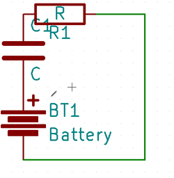
It's quite simple though. Let's go-
$$I = \frac{V_{bat} - V_C}{R}$$
And we also know from what we've learnt so far that-
$$I = C\frac{dV_C}{dT}$$
$$\frac{V_{bat} - V_C}{R} = C\frac{dV}{dT}$$
I'm gonna spare you guys the math, since I myself am quite weak at this part (You'll know why after you learn my later tutorials). I will update this once I strengthen myself here, but until then just bear with the below solution-
$$V_C = V_{bat}\left(1 - e^{-t/RC}\right)$$
Let's now discuss how capacitors behave when connected in series and parallel (and THIS you're going to be using a LOT)-
|
|
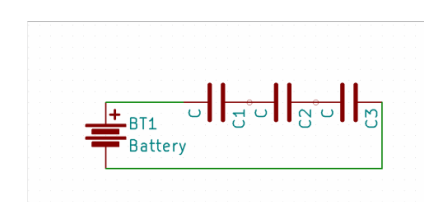
Let's start with the first image-
We know that the current is always equal in a single loop circuit like this-
$$let\; V = \sum_{i = 1}^nV_i$$
Let's consider the whole series capacitor circuit as one-
$$I = C_{net}\frac{dV}{dT}$$
$$C_{net} = \frac{IdT}{dV}$$
$$C_{net} = \frac{IdT}{dV_1 + dV_2... + dV_n}$$
$$I = C_i\frac{dV_i}{dT}$$
$$dV_i = I\frac{dT}{C_i}$$
$$C_{net} = \frac{IdT}{IdT\sum_{i = 1}^{n}\frac{1}{C_i}}$$
$$C_{net} = \frac{1}{\sum_{i = 1}^{n}\frac{1}{C_i}}$$
So you can make a capacitor of a lower value with capaciotrs you already have laying around, and that's VERY handy.
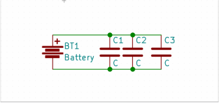
Now, let's look at the parallel Capacitor network-
$$let \; I = \sum_{i = 1}^{n}I_i$$
$$I_i = C_i\frac{dV}{dT}$$
And similarly, as before, considering the whole network as one capacitor-
$$I = C_{net}\frac{dV}{dT}$$
$$C_{net} = I\frac{dT}{dV}$$
$$C_{net} = \left(I_1 + I_2... + I_n\right)\frac{dT}{dV}$$
$$C_{net} = \frac{dV}{dT}\frac{dT}{dV}\left(\sum_{i = 1}^{n}C_i\right)$$
$$C_{net} = \sum_{i = 1}^{n}C_i$$
Which basically means you can basically create a capacitor that has a capacitance equal to the sum of the capacitors you've added, and this one is EVEN MORE usefule than the one before, so keep it in mind.
And that's it. Congratz, you've finally mastered the second comonen after a long and dread;y mathematical journey, now you've only got one more math intensive component- Inductors left before we can start with actual circuits. You've worked hard. I would treat you to a pizza, but I don't have the means to do it, so treat yourself to one, you deserve it :-)
We know that the current is always equal in a single loop circuit like this-
$$let\; V = \sum_{i = 1}^nV_i$$
Let's consider the whole series capacitor circuit as one-
$$I = C_{net}\frac{dV}{dT}$$
$$C_{net} = \frac{IdT}{dV}$$
$$C_{net} = \frac{IdT}{dV_1 + dV_2... + dV_n}$$
$$I = C_i\frac{dV_i}{dT}$$
$$dV_i = I\frac{dT}{C_i}$$
$$C_{net} = \frac{IdT}{IdT\sum_{i = 1}^{n}\frac{1}{C_i}}$$
$$C_{net} = \frac{1}{\sum_{i = 1}^{n}\frac{1}{C_i}}$$
So you can make a capacitor of a lower value with capaciotrs you already have laying around, and that's VERY handy.
Now, let's look at the parallel Capacitor network-
$$let \; I = \sum_{i = 1}^{n}I_i$$
$$I_i = C_i\frac{dV}{dT}$$
And similarly, as before, considering the whole network as one capacitor-
$$I = C_{net}\frac{dV}{dT}$$
$$C_{net} = I\frac{dT}{dV}$$
$$C_{net} = \left(I_1 + I_2... + I_n\right)\frac{dT}{dV}$$
$$C_{net} = \frac{dV}{dT}\frac{dT}{dV}\left(\sum_{i = 1}^{n}C_i\right)$$
$$C_{net} = \sum_{i = 1}^{n}C_i$$
Which basically means you can basically create a capacitor that has a capacitance equal to the sum of the capacitors you've added, and this one is EVEN MORE usefule than the one before, so keep it in mind.
And that's it. Congratz, you've finally mastered the second comonen after a long and dread;y mathematical journey, now you've only got one more math intensive component- Inductors left before we can start with actual circuits. You've worked hard. I would treat you to a pizza, but I don't have the means to do it, so treat yourself to one, you deserve it :-)
