The Basics of the Basics
Prerequisites:
- Nothing
Let's get into this stuff and get it over with. Let's first of all start with what voltage actually is-
Voltage, often called potential difference is the work done per unit charge
Well that's a bit hard to understand, but in easier terms, it means that voltage is the energy supplied to each electron or rather coulomb (just a unit of charge). Don't worry if you still don't get this (but I'd definitely urge you to relearn a bit of highschool physics) since you'll never need this.
As for current, well-
Current is the number of charges passing through any point in a conductor, per unit time. Mathematically I = Q/T where I is the current, Q is the number of charges, T is the time
I don't think there's anything to explain, but you can think of it as the "speed" of the charges.
Let's now talk about current. To be exact, how it flows. If you remember being taught that negative charges (electrons) constitute electric current, then you were taught right. Basically, what this means is that charges flow from the negative terminal to the positive. If you're thinking "Hey, wait a minute, isn't it the other way around?". No. It isn't. But it's taken to be so, because convention. So, from here on, I'm going to talk about the conventional flow of current whenever I say current.
And now about schematics-
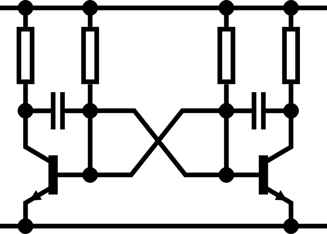
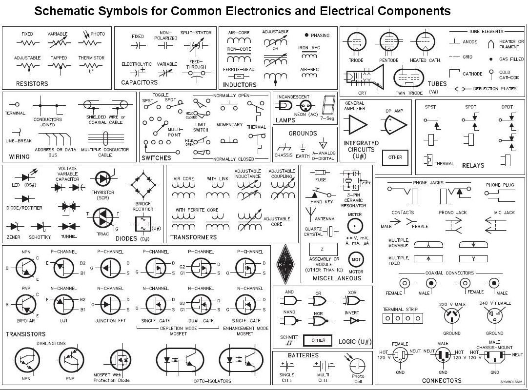
What you're seeing above is called a schematic, a great way of representing circuits without having to show the possibly horrible and unneat circuit you've actually made. A line going from point to point represents a wire, and different symbols represent different components. If you're new to this stuff, you might wanna get comfortable with this, since this is how every example circuit I'm going to show you is going to look like. Below are a few symbols that you can use for reference (Protip: Don't try to cram them. You'll learn what's what along with time)-